 Fraunhofer Institute for Wind Energy Systems
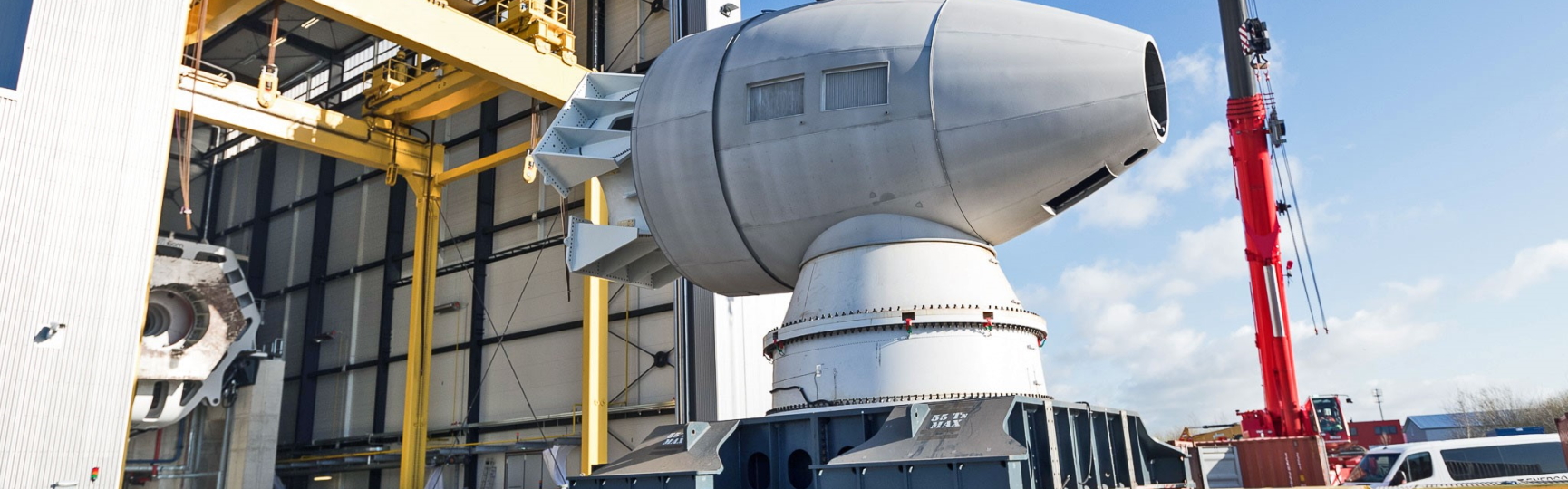
Mechanical models help to minimize risks during development as well as operation and increase the efficiency of wind turbines.
The IWES simulation models – reliable and efficient
Expertise and analysis for full turbine simulation
Simulation of the dynamic drive train and its components
Calculation of the load distribution in the large bearing for wind turbines
Support and foundation structures
Our services in mechanical modeling of wind turbines and their components
Fraunhofer IWES has developed a simulation model (MoWiT) for the load calculation of wind turbines and real-time simulation in a Hardware-in-the-Loop environment. With it, it is possible to take into consideration wind turbine components such as structural components, aerodynamics, turbine control, and much more. For the drive train, for example, any operating conditions can be simulated with an increased degree of detail via coupling with the full turbine simulation. The load distribution in the large bearing is reliably determined utilizing the finite element method. IWES contributes to increasing the efficiency and reliability of the support and foundation structures with customized mechanical models.
Fraunhofer IWES conducts research in the field of the aero-servo-hydro-elastic simulation of wind turbines and has extensive expertise in the modeling and load analysis of wind turbines taking into consideration the requirements of international standards (GL, IEC).
To this end, a simulation model (MoWiT) was developed for the load calculation of wind turbines and real-time simulation in a Hardware-in-the-Loop environment. This model was programmed in the object-oriented open source modeling language Modelica and saved in a component-based library. The library contains models for structural components, aerodynamics, turbine control, drive trains, environmental conditions, and offshore simulations. It enables the running of aero-hydro-servo-elastic simulations of wind turbines, which can be analyzed by the simulation environment in the time domain. The models are divided into wind turbine components as shown in the following representation of an offshore wind turbine.
This newly developed tool is used to optimize offshore wind turbines from a system perspective employing a Python-based optimization framework. MoWiT has been used to develop a generic wind turbine model with a capacity of 7.5 MW, which can be found here: Overall system measurement and simulations
IEA Task 30 OC4 Phase II floating semi-submersible offshore wind turbine in MoWiT © Fraunhofer IWES

Any operating conditions for the drive train can be realistically simulated with an increased degree of detail via coupling with the full turbine simulation. Depending on the degree of detail required, this is achieved using multi-body simulation supplemented with the finite element method. IWES boasts extensive and diverse methodological expertise thanks to its many years of experience in the field of the modeling, testing, and validation of drive trains and their components.
On the one hand, existing components can be modeled in a more cost-efficient and resource-saving manner with regard to improved or new manufacturing processes – more precise knowledge of the design boundary conditions such as loads and deformations is available for this purpose. On the other hand, higher-quality mechanical models enable the appropriate design of real and experimental structures for the investigation of test objectives or failure mechanisms defined in advance. Innovative test methods such as the “Hybrid Testing” method (patent pending) require a detailed mechanical model for it to be possible to obtain valid statements for the full load range. This applies for the experimental partial load testing of real-scale components or systems as well as the increasingly important testing of scaled test objects.
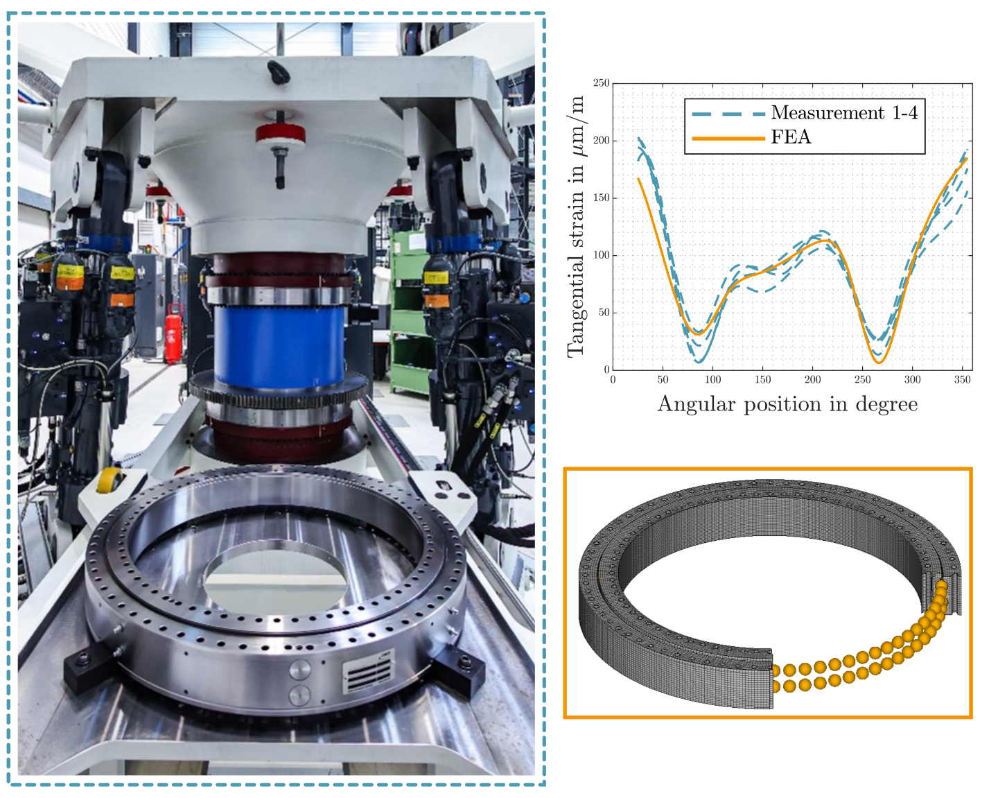
The adjacent components have a significant influence on the loading of large bearings in wind turbines. The load distribution in the bearing can only be reliably determined utilizing the finite element method. The high number of rolling contacts, the variety of possible load situations, and the geometric complexity of the adjacent components render it necessary to find a compromise between the degree of detail of the modeling and the computing time of the models.
A wide range of scientific papers, practice-oriented books, and the revision of the “Wind Turbine Design Guideline 03 on Yaw and Pitch Bearings” have already been published at IWES on this topic. One of the focuses is on the validation of the models by means of tests. The image shows a comparison of simulation and test results on the BEAT1.1 test rig. The graph displays the results of the measurements of different bearings of the same type and the finite element (FE) simulation.
Further focuses include the reduction of necessary simulations through load case selection and subsequent interpolation, the simulation of complete rotors to determine the interactions between individual rotor blade bearings, and the transfer to simplified test setups. The modeling generates the input data for the calculation of the static load as well as the fatigue of the structure and rolling contacts of large bearings. The data generated can also be used to predict frictional torques using artificial intelligence (AI).
At least 30% of the investment costs for a wind turbine (and often far more) are associated with the support structure – comprising tower and foundation, both onshore and offshore. IWES utilizes customized mechanical models to help increase the efficiency and reliability of these largest and most massive components of the full turbine, bring innovations to the market more quickly, and minimize risks during development and operation.
Current focuses include the soil-structure interaction between the foundation and subsurface, low-noise and efficient foundations and installation techniques, the buckling behavior of towers and suction buckets, and the operational stability of thick-walled welded components with wall thicknesses of more than 100 mm. The experimental mechanical models are supplemented with and complemented by validated numerical simulation methods, which enable the transfer and scaling of the findings from the large-scale tests to real turbines.
A geotechnical test pit measuring 10 m in depth by 14 m in length and 9 m in width is available at the Test Center Support Structures (TTH), a joint facility of the Leibniz University Hannover and IWES, in which typical North Sea subsoil can be installed for mechanical testing of various foundation types. An additional span allows the testing of large steel and concrete components with loads of up to 2 MN per hydraulic test cylinder.
Suction bucket installation in the geotechnical test pit © Fraunhofer IWES